Quick snapshot: 5‑pin DIN connector assembly, shielded round cable, nominal length 2.00 m ±50 mm, cable O.D. ≈ 5.4 mm, beige molded housing with strain relief. Commonly used for legacy keyboard/control interfaces, bench test rigs, and low‑frequency signal harnesses. This document provides the full AK306-2 pinout, mechanical highlights, electrical limits, test procedures, installation best practices, and ready‑to‑use pin tables and wiring cards for US engineering teams.
1 — Background & Product Overview
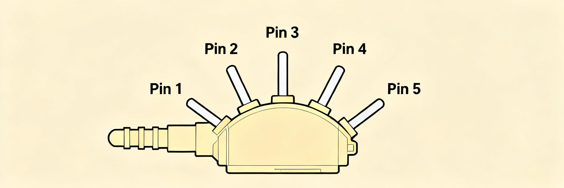
Specification summary
Type: 5‑pin DIN, circular cable assembly; Connector genders: male/female options; Pins: 5; Shielded: braided drain with PVC jacket; Nominal length: 2.00 m ±50 mm; Color: beige; Molded strain relief. Refer to the AK306-2 datasheet for full mechanical drawings and approved material callouts.
Typical applications & compatibility notes
Primary uses: legacy keyboard interfaces, control panel connections, audio/control interconnects, and automated test fixtures. Mating connectors: standard 5‑pin DIN male/female (180° or 240° variants—verify orientation). Compatibility checklist: match shell diameter, pin orientation, and shield termination method before integration; confirm coaxial/impedance needs if adapting for higher‑frequency signals.
2 — Key Electrical Specifications & Ratings
Electrical limits & signal characteristics
Typical electrical envelope (per manufacturer guidance): maximum working voltage ~50 V DC, recommended current per contact ≤1 A for continuous operation, contact resistance ≤50 mΩ typical, insulation resistance ≥100 MΩ at 500 V DC. This assembly is intended for logic/audio level signals rather than power distribution or RF; avoid sustained currents above recommended limits and derate at elevated temperatures.
Environmental & thermal ratings
Operating temperature range commonly specified: −20 °C to +70 °C; storage: −40 °C to +85 °C. Cable jacket is PVC or similar; check datasheet for flammability/UL claims—if no UL rating is listed, treat as general‑purpose. Humidity and altitude: suitable for typical indoor lab and industrial environments; for sealed or outdoor use, specify alternate jacketing or sealing methods.
3 — Physical Dimensions & Mechanical Details
Connector & cable mechanical drawing highlights
Key mechanical notes: 5‑pin DIN shell diameter (standard range) fits standard panel cutouts; pin pitch and radial spacing follow DIN pattern—confirm with mechanical drawing. Cable O.D. ~5.4 mm; molded housing includes integrated strain relief and keying to prevent misorientation. Recommend including a scaled DWG/STEP for assembly tolerance checks and clearance planning.
Packaging, marking & lead length tolerances
Common packing: bulk reels or bagged sets with label ID and part number. Color: beige molding; part marking typically includes part code and lot. Nominal lead length 2.00 m with tolerance +50 mm; order part‑number suffixes for length variants. Specify revision, tolerance band and units on purchase orders to ensure correct variant delivery.
4 — Electrical Pinout & Signal Mapping
Pin table (engineer-ready)
The AK306-2 pinout below is provided as a ready reference. Verify pin numbering orientation with the physical mating face before wiring. Typical per‑pin DC resistance values assume clean contacts and short conductor length.
| Pin | Physical location | Wire color | Function | Typical R (Ω) |
|---|---|---|---|---|
| 1 | Leftmost (viewed from mating face) | White | Signal A / Rx | ≤0.05 |
| 2 | Upper | Green | Signal B / Tx | ≤0.05 |
| 3 | Rightmost | Red | Vcc or auxiliary | ≤0.10 |
| 4 | Lower | Blue | Ground return / GND | ≤0.05 |
| 5 | Center | Black | Shield drain / NC | ≤0.05 |
CSV (machine readable):
Wiring examples & mapping scenarios
Scenario A — straight‑through keyboard: match pin numbers 1→1, 2→2, etc.; tie shield to chassis at one end only to minimize ground loops. Scenario B — custom test harness: repurpose pin 3 as +5 V supply, pin 4 as ground; route shield to instrument chassis and add ferrite bead near connector for noise suppression. Always verify polarity and perform continuity before powering circuits.
5 — Testing, Validation & ESD Considerations
Recommended test procedures
Minimum test sequence: 1) continuity check for each conductor (<0.1 Ω expected), 2) contact resistance via 4‑wire method (≤50 mΩ pass), 3) insulation resistance ≥100 MΩ at 500 V DC, 4) short‑to‑shield test (no shorts), 5) mechanical pull test on strain relief (per contract spec), 6) flex/cycle test (1000 cycles typical for qualification). Use calibrated DMM, LCR meter or micro‑ohmmeter and document results against pass/fail criteria.
ESD handling & quality control checkpoints
ESD: use wrist straps, ionizers, and grounded workstations when handling exposed contacts. Incoming QC: visual inspection for mold flash, cable O.D., length tolerance, connector seating, and correct wire colors. Sample test plan: 1 in 50 units continuity and insulation checks; 100% visual and length verification on receipt.
6 — Installation, Wiring Best Practices & Common Faults
Installation checklist & routing tips
Routing: maintain minimum bend radius ≥5× cable O.D. (~27 mm for 5.4 mm OD) and avoid sharp bends at the strain relief. Terminate shield to chassis at a single point; avoid bundling with high‑current conductors. Secure connector with proper retention hardware and add a retainer or cable clamp to remove mechanical load from the connector body.
Troubleshooting guide (symptom → probable cause → fix)
| Symptom | Probable cause | Fix |
|---|---|---|
| No signal | Open conductor | Continuity check → reterminate or replace |
| Intermittent | Poor contact or strain on conductors | Inspect pin seating, retension connector |
| Noise/crosstalk | Shielding not tied or wrong routing | Terminate shield properly, reroute away from noisy lines |
7 — Quick Reference: Pin Table, Wiring Diagrams & Checklist
Compact quick-reference cards to include with product
Create two one‑page assets for field deployment: (1) printable pinout card showing connector face, pin numbers, colors and functions; (2) single‑line wiring diagram with shield termination and recommended connector orientation; (3) short acceptance test checklist with continuity, insulation, and mechanical checks.
Suggested downloadable assets & naming conventions
Recommended files: PDF datasheet named "AK306-2_Datasheet_revA.pdf" (include revision, units, tolerance table), mechanical DWG/STEP "AK306-2_mech_revA.step", and PNG wiring diagram "AK306-2_wiring_card.png". Each asset should include revision, drawing scale, units (inches for US), and a clear date code labeled as "Current".
Summary
Key takeaways: the AK306-2 pinout targets shielded 5‑pin DIN low‑voltage signal use with nominal 2.00 m length and ~5.4 mm cable O.D.; verify pin orientation and shield termination before integration. Prioritize continuity, contact resistance, and mechanical strain tests as top validation steps. Add the AK306-2 pinout and AK306-2 datasheet references to your BOM and test plan to complete procurement and QA readiness.
Frequently Asked Questions
What is the AK306-2 pinout for typical keyboard wiring?
Typical keyboard wiring uses straight‑through mapping: match mating pin numbers 1→1 through 5→5, tie shield to chassis at one end, and verify that pin designated for ground is connected to the system ground. Always confirm orientation on the mating face before soldering or crimping.
Can AK306-2 carry power for small devices?
AK306-2 assemblies are intended primarily for low‑voltage, low‑current signals. While short bursts of low current (≤1 A) are acceptable, continuous power delivery above recommended limits risks contact heating; if you need higher current, specify a power‑rated connector variant.
How should the shield be terminated for best noise performance?
Best practice: terminate shield to chassis ground at one end only to avoid ground loops; use a short drain wire soldered or crimped to the shell or a dedicated grounding lug. For sensitive measurements, add ferrite or RC filtering near the connector.
What are the key electrical limits and temperature ratings for the AK306-2?
The AK306-2 features a maximum working voltage of ~50 V DC, a recommended continuous current of ≤1 A per contact, contact resistance ≤50 mΩ, and insulation resistance ≥100 MΩ at 500 V DC. The specified operating temperature range is −20 °C to +70 °C.


