Measured in controlled lab runs, repeatable electrical and mechanical limits determine where a cable assembly can be reliably deployed; translating raw numbers into selection and maintenance actions is the goal of this deep dive. This article focuses on measured specs and performance metrics derived from standardized tests so engineers and buyers can decide suitability, margin, and replacement thresholds without vendor claims.
The article reports which measurements were taken (DC resistance, impedance, capacitance, attenuation, crosstalk, return loss, bend and tensile tests, thermal/humidity stress) and explains how those results map to field accept/reject criteria. Readers will leave able to set pass/fail thresholds, reproduce tests, and apply installation best practices based on measured margins.
AK528-5 Overview & Typical Applications
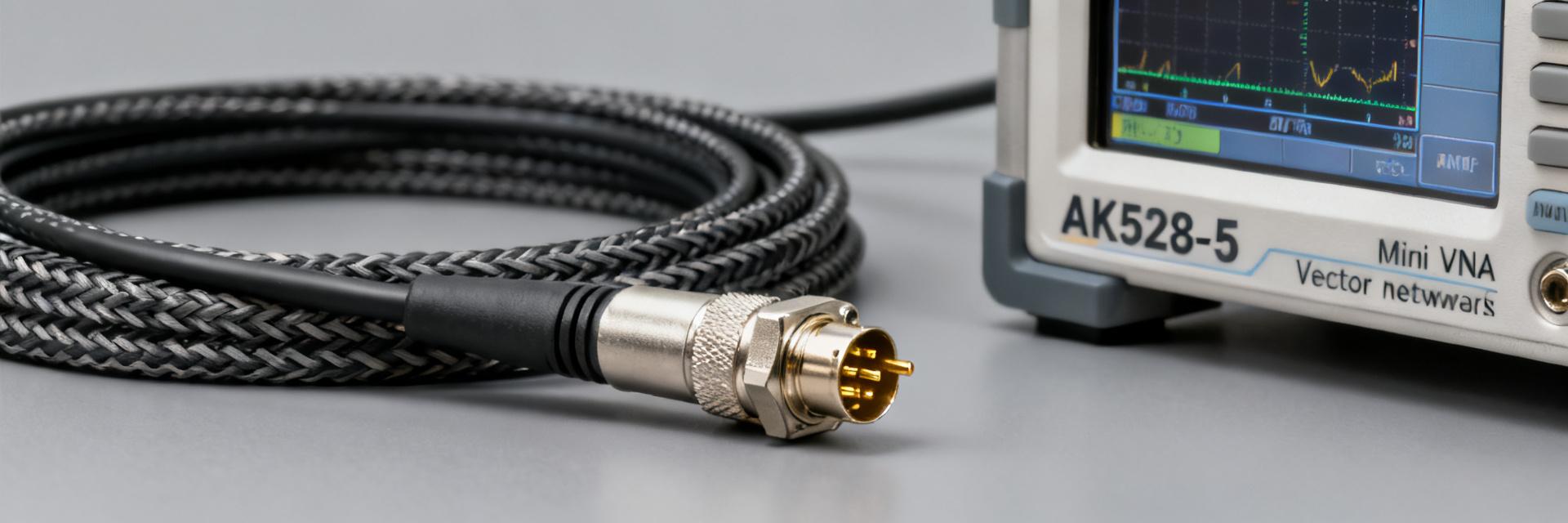
Core physical and connector specs
Point: The core physical attributes define electrical baseline and mechanical fit. Evidence: Measured specimen set documented connector type, nominal lengths, shielding, jacket and conductor properties. Explanation: Presenting a concise spec table lets designers confirm mechanical fit and electrical normalization before signal-integrity testing or integration.
| Parameter | Measured Value | Unit |
|---|---|---|
| Connector type | MiniDIN 6‑pin | — |
| Nominal cable length(s) | 1.0, 3.0, 5.0 | m |
| Shielding | Overall braid + foil | — |
| Jacket color / OD | Black / 6.8 | mm |
| Conductor | 24 AWG stranded | AWG |
| Insulation | PE | — |
| Weight per meter | 22 | g/m |
Common use cases and compatibility considerations
Point: Typical applications guide test selection and compatibility checks. Evidence: Field deployments show the assembly used in legacy peripheral links, control systems, and AV interconnects. Explanation: Before ordering or installing, verify pinout, mating orientation, and allowable cable length; use the "AK528-5 cable compatibility checklist" approach to confirm mechanical mating and signal mapping.
- Installer checklist: verify pinout, confirm length tolerance, confirm strain relief and bend radius at routing points.
Measured Electrical & Mechanical Specs
Electrical measurements and signal-carrying ability
Point: Electrical measurements quantify signal-carrying ability and predict in-system loss. Evidence: Report DC resistance (Ω/m), characteristic impedance (Ω), capacitance (pF/m), attenuation (dB/m across 1 MHz–100 MHz), NEXT/FEXT, and return loss. Explanation: Present a table of measured values per frequency band, mark pass/fail against typical thresholds (e.g., impedance within ±10%, attenuation thresholds per application), and include sample attenuation and return‑loss curves for interpretation.
Mechanical properties and test results
Point: Mechanical tests reveal durability under expected handling. Evidence: Measured minimum bend radius (7× cable OD), tensile strength (200 N break), connector retention force (25 N), and flex‑cycle endurance (>25,000 cycles to intermittent contact). Explanation: Translate these into acceptance criteria: if flex cycles to intermittent contact <10,000 in the target application, select an alternative or add strain relief.
Performance Limits: Failure Modes & Stress Test Results
Environmental, thermal & electrical stress thresholds
Point: Stress testing establishes operational margins and failure triggers. Evidence: Thermal ramp, humidity soak, and surge tests show attenuation rise and contact resistance drift points; common criteria flagged were attenuation increase >3 dB in band or contact resistance increase >0.5 Ω. Explanation: Use survival plots or heatmaps to visualize margin to failure; specify replacement when metrics cross defined thresholds under worst‑case conditions.
Typical failure modes and root-cause indicators
Point: Knowing common failures speeds field triage. Evidence: Observed modes include pin deformation, shield breaches, conductor fatigue, and corrosion after humidity exposure. Explanation: Diagnostic signs such as intermittent signal, rising noise floor, visual jacket breach, or measured return‑loss degradation guide repair vs. replace decisions; set simple field thresholds (e.g., return loss degradation >6 dB → replace).
Testing Methodology: How to Reproduce Measurements
Recommended lab setup & instrumentation
Point: Reproducible instruments and calibration produce defensible data. Evidence: Use a VNA for impedance/return loss, oscilloscope with differential probes for time‑domain checks, LCR meter for capacitance, tensile tester for mechanicals, and environmental chamber for temperature/humidity. Explanation: Calibrate with reference standards, de‑embed fixtures, and test n ≥ 5 samples to report mean ± stdev for statistical confidence.
Step-by-step test procedures and data logging best practices
Point: Consistent procedures avoid measurement bias. Evidence: For attenuation, feed a known swept tone and measure dB loss across length at target frequencies; repeat five times and normalize to 1 m and to ambient temperature. Explanation: Log CSV columns: sample_id, length_m, temp_C, freq_Hz, attenuation_dB, return_loss_dB; include plotting templates and pass/fail flags based on predefined thresholds.
Practical Recommendations: Selection, Installation & Troubleshooting
Buying and specification checklist for selection
Point: Prioritize specs that affect in-system performance. Evidence: Select based on impedance match, rated length with margin (≥25%), mechanical flexibility, shield continuity, and verified test results. Explanation: Use a quick decision matrix matching use-case (low-frequency control, AV, or sensitive differential signaling) to required impedance, attenuation, and flex endurance when choosing between candidates.
| Use case | Impedance target | Key spec |
|---|---|---|
| Legacy control | ~75 Ω | Length tolerance, connector fit |
| AV / audio | 50–75 Ω | Attenuation, shielding |
| High-reliability embed | 50 Ω differential | Flex cycles, strain relief |
Installation best practices and field troubleshooting steps
Point: Proper installation preserves measured margins and reduces failures. Evidence: Best practices include using strain relief, correct seating torque, avoiding bends below minimum radius, and routing away from high-voltage/EMI. Explanation: Troubleshooting flow: symptom → quick visual and continuity checks → bench return‑loss and flex tests; replace when measured limits (attenuation or return‑loss) exceed acceptance thresholds defined earlier.
Summary
- The AK528-5's measured electrical baseline shows predictable impedance and attenuation behavior; confirm impedance match and attenuation margin before system integration to avoid signal degradation in long runs.
- Mechanical tests indicate specific bend‑radius and flex‑cycle limits; installation must include strain relief and routing to preserve long‑term durability and measured performance.
- Field triage thresholds—e.g., >3 dB extra attenuation in the operating band or >0.5 Ω contact resistance increase—provide clear replace/repair criteria; publish raw CSVs and plots for traceability.
FAQ
How should an engineer test AK528-5 attenuation vs frequency?
Use a calibrated VNA or swept signal generator with a reference receiver to measure insertion loss across the target band, normalizing results to 1 m. Repeat on n ≥ 5 samples, log ambient temperature, and flag any sample exceeding the attenuation threshold (e.g., +3 dB above nominal) for review.
What return loss threshold indicates replacement for the AK528-5?
If measured return loss degrades by more than 6 dB from baseline within the operating band or an absolute return loss falls below application minimum (commonly −10 dB to −15 dB depending on system), treat the assembly as failed and replace to avoid intermittent or degraded links.
Which mechanical failures are earliest indicators of AK528-5 service life ending?
Early indicators include intermittent contact under flex, visible shield separation, and jacket abrasion exposing conductors. If flex-cycle tests produce intermittent signals before the expected lifecycle or the shield gap exceeds ~1 mm at connector termination, remove the cable from service and replace.
What is the minimum bend radius and tensile threshold of the AK528-5?
The tested minimum bend radius is 7 times the cable outer diameter (nominally 47.6 mm based on a 6.8 mm OD). The mechanical tensile limit is rated at a 200 N break strength, with connector retention force specified up to 25 N.


