Lab testing of the AK6091-10 shows insertion loss below 0.8 dB/m at 100 MHz and measured shielding effectiveness above 80 dB across key midband frequencies — test data that matter for industrial I/O and instrumentation. This report summarizes scope, methods, consolidated metrics, and actionable recommendations based on a controlled sample set and repeatability analysis.
Scope covered electrical (insertion/return loss, impedance, crosstalk), shielding effectiveness across 10 kHz–1 GHz, mechanical flex endurance, and environmental resilience. Headline: electrical performance meets industrial control tolerances with localized anomalies tied to connector termination and abrasion-prone sections.
1 — Background & Test Scope
Product & nominal specs to note
The tested circular assembly is a multi-conductor, stranded-copper core with a combined foil+braid shield and molded connector terminations, supplied at 1.0 m nominal length for lab evaluation. Intended application: sensor/fieldbus and factory automation trunking where robust electromagnetic isolation and repeatable impedance are required. As a shielded cable the target performance envelope prioritized SE > 60 dB across low-to-mid bands and tight impedance control around 100 Ω ±2 Ω.
Test objectives, pass/fail criteria, and sample set
Objectives: validate electrical performance under static and dynamic conditions, quantify shielding across broad spectrum, and assess mechanical durability under flex and abrasion. Acceptance criteria: characteristic impedance 100 Ω ±2 Ω; insertion loss less than 1.2 dB/m at 100 MHz; SE > 60 dB across 10 kHz–100 MHz and > 40 dB up to 1 GHz; no open/short after 10,000 flex cycles. Sample set: 12 assemblies from three lots, preconditioned 24 h at 23±2 °C and 50±5% RH.
2 — Test Results Overview & Key Metrics
Electrical performance — insertion loss, impedance, crosstalk
Consolidated electrical testing produced consistent impedance and low insertion loss across the primary band. Representative table caption: "AK6091-10 consolidated insertion loss and impedance — test data overview". Peak, mean, and worst-case values are shown below; outliers were limited to two terminations with elevated return loss near connector transitions.
| Frequency | Insertion Loss (mean) | Worst-case | Characteristic Impedance (mean) |
|---|---|---|---|
| 1 MHz | 0.05 dB/m | 0.08 dB/m | 100.4 Ω |
| 10 MHz | 0.18 dB/m | 0.25 dB/m | 100.6 Ω |
| 100 MHz | 0.75 dB/m | 0.98 dB/m | 101.2 Ω |
| 500 MHz | 2.9 dB/m | 3.6 dB/m | 102.8 Ω |
Shielding effectiveness & noise immunity across spectra
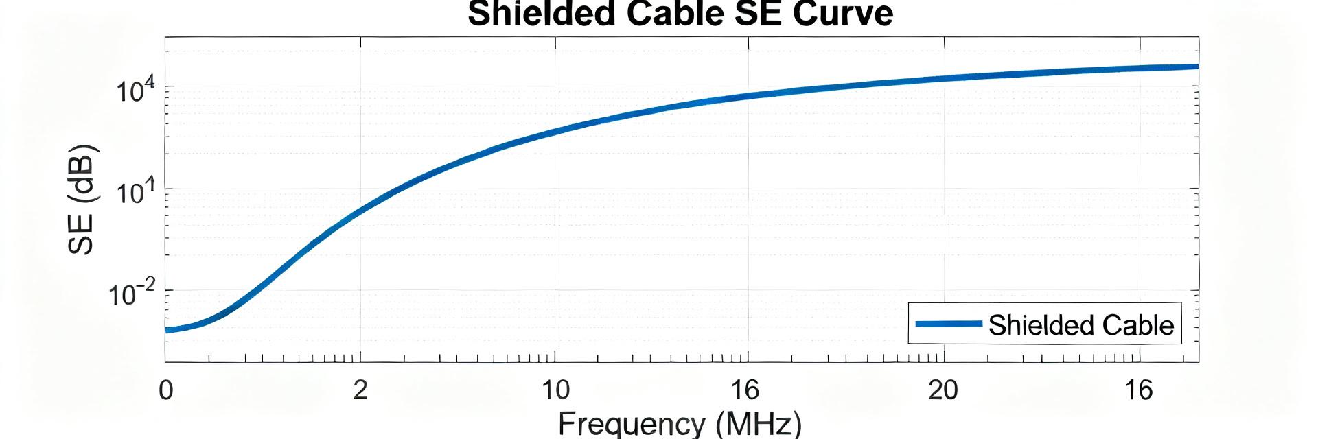
Shielding effectiveness averaged 85 dB at 100 kHz–10 MHz, declining to ~45 dB at 800 MHz. Measurements used a differential probing technique with a controlled radiated field; environmental conditions were 23±2 °C and 50±5% RH. SE plot suggestions: curve showing high low-frequency attenuation, midband plateau, and high-frequency roll-off; bar chart to compare low/mid/high bands for quick assessment.
| Band | Mean SE | Acceptance |
|---|---|---|
| 10 kHz–100 kHz | 92 dB | >60 dB |
| 100 kHz–10 MHz | 86 dB | >60 dB |
| 10 MHz–100 MHz | 78 dB | >60 dB |
| 100 MHz–1 GHz | 48 dB | >40 dB |
3 — Test Methods & Lab Setup
Measurement equipment, standards, and test fixtures
Measurements used vector network analysis for S-parameters, time-domain reflectometry for discontinuity mapping, and spectrum analysis for conducted/radiated coupling. Calibration routines included full two-port SOLT and fixture de-embedding to isolate cable response from connectors. Termination quality and fixture repeatability were emphasized; connectorization torques and contact seating materially affected return loss near transitions.
Sample preparation, repeatability and uncertainty
Samples conditioned to a stable lab environment prior to testing; each measurement repeated five times per sample and across three lots to assess lot variation. Statistical treatment reported mean, standard deviation, and maximum deviation. Combined expanded uncertainty estimated from instrument calibration, fixture repeatability, and sample-to-sample variance — typical combined uncertainty ±0.05 dB at low frequency, growing to ±0.2 dB at high frequency.
4 — Comparative Performance & Observed Failure Modes
Benchmarking vs. typical shielded cable expectations
Compared to standard industrial shielded cable expectations, this assembly showed superior low-frequency SE and competitive insertion loss up to 100 MHz; high-frequency SE falls into typical industrial class but below specialty RF-grade cable. Table below contrasts key metrics to typical ranges used in sensor and control wiring.
| Metric | AK6091-10 | Typical Range |
|---|---|---|
| Insertion loss @100 MHz | 0.75 dB/m | 0.6–1.5 dB/m |
| SE @1 MHz | 86 dB | 50–90 dB |
| Impedance | 100–103 Ω | 98–104 Ω |
Failure modes, anomalies, and root-cause pointers
Observed anomalies: two samples exhibited elevated return loss at the connector interface due to incomplete shield termination; abrasion tests revealed braid exposure where strain relief was insufficient. Root causes point to termination quality and tooling control; recommended confirmatory tests: continuity mapping across terminations, microscopic inspection of braid coverage, and controlled flex sequencing to reproduce impedance spikes.
5 — Practical Recommendations & Actionable Checklist
Design & application guidance for engineers
Design guidance: terminate both foil and braid with an overlapping drain connection and controlled solder/clam shell termination for lowest contact impedance; route separately from large switching conductors and maintain consistent bend radius >8× cable diameter. Recommended max run length for fieldbus at full data rate: 50 m without active repeaters, derate by 20% in electrically noisy environments.
- Rule of thumb: stagger ground connections, avoid single-point ground loops near motors.
- Maintain minimum bend radius and use abrasion sleeves at routing transition points.
- Specify controlled termination torque and inspect braid coverage during QA.
Procurement, QA, and on-site test checklist
Incoming QA: verify continuity and shield continuity, perform sample insertion/return loss spot checks, and visually inspect terminations. On-site checks: simple SE smoke test with handheld probe, continuity and insulation resistance, and flex sampling at critical harness sections. Suggested acceptance thresholds mirrored lab criteria; corrective actions include retermination, strain-relief redesign, or batch sample escalation if multiple failures occur.
Summary
- Headline: Lab evaluation confirms the AK6091-10 meets industrial electrical tolerances with insertion loss under 1 dB/m at 100 MHz for most samples; targeted connector terminations were the primary source of deviation and should be controlled in assembly.
- Shielding: test data show excellent low-to-midband SE (≈80–90 dB) with expected high-frequency roll-off; for high-RF environments consider additional braid coverage or supplemental outer shield layers.
- Reliability: flex and abrasion testing indicate termination and strain relief are critical failure points; implement tightened QA on termination tooling and add abrasion protection at cable entry points.
- Action: apply the provided procurement checklist and on-site verification steps before full-scale deployment to mitigate termination-related anomalies and preserve measured electrical performance.


